Double Balanced Mixers
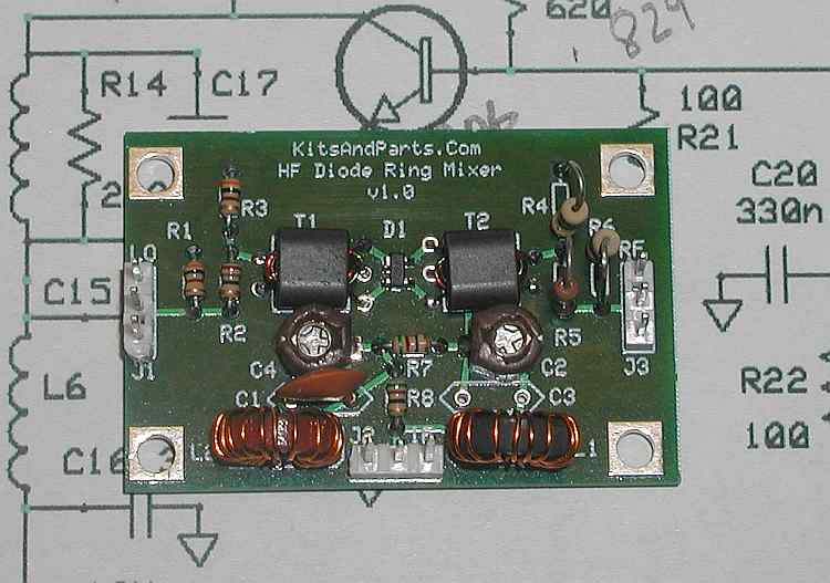
We are going to take a look at the characteristics of a double balanced mixer. We will use this one as an example because I have one and can run tests on it. This particular board is available as a kit containing all parts from Kits and Parts for $8.00.
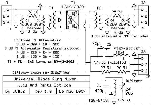
Here's what the board looks like. The tuned circuits in the lower right corner are diplexers. Their job is to forward the desired frequencies out the IF port and absorb the other frequencies. If the undesired frequencies aren't absorbed by the load resistors, they will be reflected back into the mixer and create problems.
Here's a picture of the board. It is designed for a +7dbm VFO input on J1 with the RF signal in on J3 and the 5.067 Mhz IF output on J2.
First lets talk about some different types of mixers. One is a single diode, unbalanced mixer. About the only advantage it has is it is cheap and very simple. The output will contain all input frequencies, the harmonics of the input frequencies, and all of the sums and differences of these frequencies. For our purposes, that's not very good.
The next stage of complexity is the single balanced mixer. This mixers output will suppress either the RF input or the VFO input. It will contain all of the frequencies above except the RF or VFO frequency products. Better but still not great.
Now we get to the one shown above. The double balanced mixer. It's output will suppress both the VFO and RF input frequencies. As if that wasn't good enough, it also suppress's the even order harmonics of the VFO and RF input frequencies. That eliminates a lot of different frequency combinations at the output.
Lets take a look at some of these claims. First, we will input into the mixer only the VFO voltage at +7dbm power. There is no RF signal at this time.
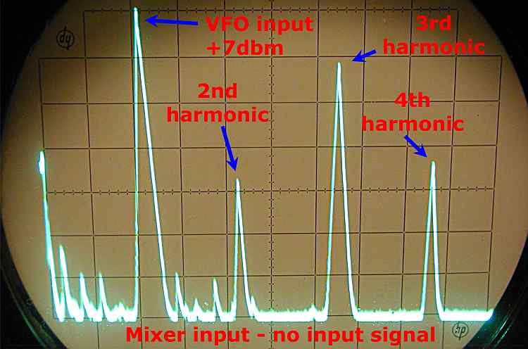
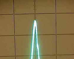
Above we are looking at the mixer input signal at the VFO port. The VFO frequency is 2.1 Mhz and each horizontal division is 1 Mhz. Each vertical division is 10db. There is a lot of harmonic content here.
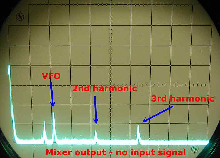
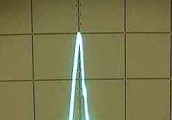
This is the output of the mixer. All of the VFO products are highly attenuated.
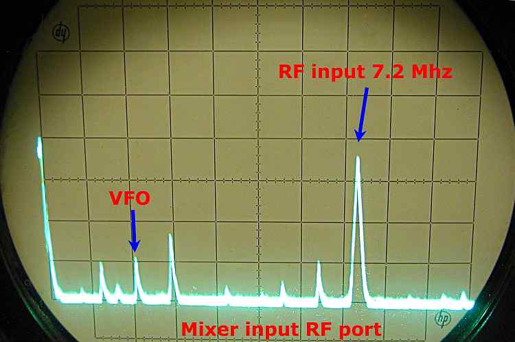
Above is the output of our signal generator at the RF input port of the mixer. The signal level being inserted is -40dbm. That's 47 db lower than the VFO input but notice how little VFO signal is being fed back out the RF port. DBM's have very good port-to-port isolation. Lets look at the output of the mixer.
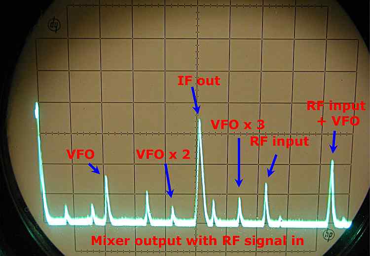
Notice that the IF output is almost the same level as it was on the input. No settings have been changed from the picture above. That says there is very little loss in the frequency conversion. You can also see the other frequencies that are at the output. It is the job of the IF filter to get rid of these.
Lets take a more detailed look at mixer loss or conversion loss.
 |
The conversion loss chart for the HSMS-2829 mixer diodes show that the lowest amount of conversion loss will occur when the local oscillator power is around +7dbm. That works out great as I have the VFO power output set to +7dbm. Looking across horizontally the predicted loss is about 6.5 db. |
|
RF input level 7.1 Mhz |
IF output level 5.067 Mhz Each minor division is 2db. We are showing about -4db. I would guess that we just have a measurement error and the loss probably is about -6.5 as predicted. At least we don't see any major difference from the predicted values. It must be working properly. |
|