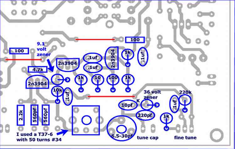
The VFO section stands on it's own and will be easy to test so I choose that as the next section. A transformer was furnished with the boards but it would have to be rewound as the VFO needed about 9uh's of inductance and the transformer maxed out around 5uh. Depending on the variable capacitor you tune with, the turns on the inductor may have to be adjusted but 50 should be plenty and then you can remove some to adjust the frequency up. My test capacitor tuned from 15-377pf and the VFO had almost a 500khz tuning range so setting the frequency shouldn't be really critical. I didn't tweak the range on mine as I will do that when I install it into a case.
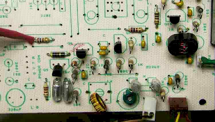
Next I assembled it and connected my oscilloscope to the output. You can see the power connection for the test
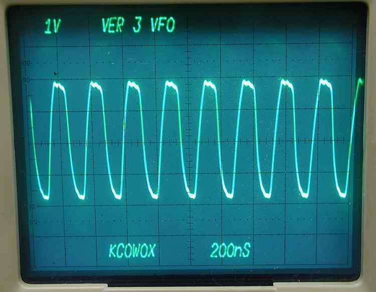
I checked it out with the scope. A little over 3.5 volts. This will be less when the transformer is hooked up due to it's loading. There is some distortion of the sine wave so we know there is some harmonic content.
A quick look with the spectrum analyzer to see what the 2nd harmonic looks like.
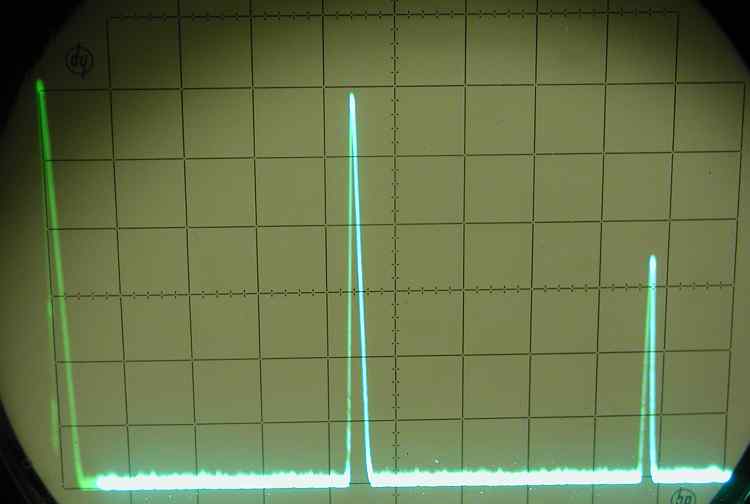
1 Mhz/div horizontal. The left is 0hz and the right is 10mhz. Each vertical division is 10db. It looks like the 2nd harmonic is down about -25db.
Time to drink a cool one and then pick a new section to do next.