Great designs don't always work
out
or
How to not make the same mistakes
I did!
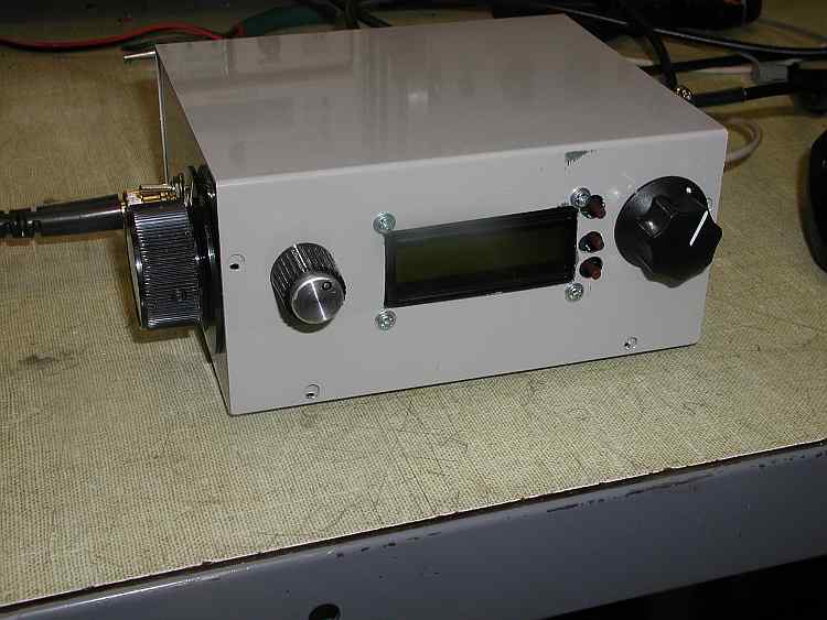
Now that the testing is completed and everything works, the last step is to put the board into an enclosure. Here is the plan.
The left front panel knob is the volume and the right is the fine tune. The frequency readout is a Norcal FCC-1.
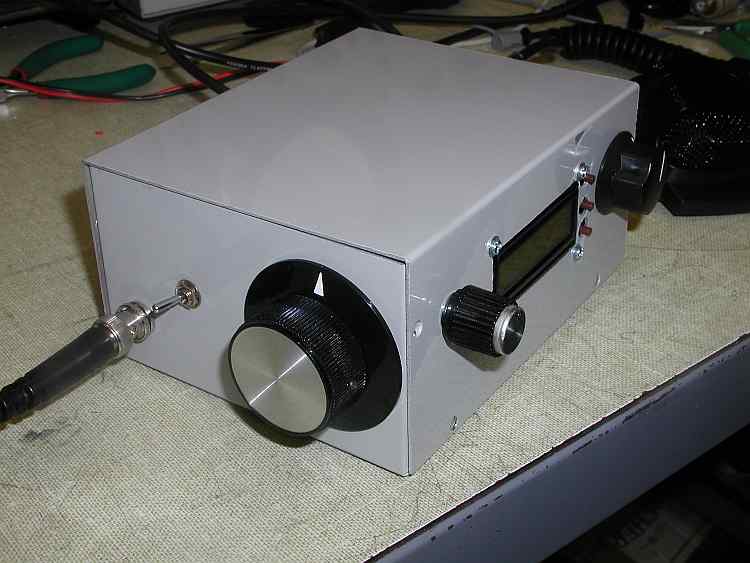
The big knob on the left side is the frequency tuning. With a big knob, the tuning is easy enough that many times when changing frequency, fine tuning adjustment is not needed. If it is, frequency tuning with both hands is easily accomplished. The switch offsets the frequency so in the position shown, it tunes 14.146 to 14.228. In the forward position, it tunes 14.112 to 14.356. The connector is the antenna connection.
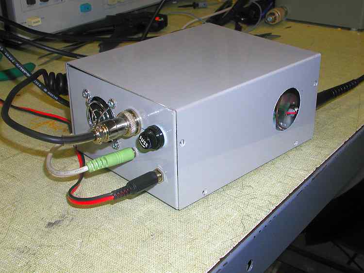
The other side has a small fan, the microphone connector, the speaker output jack, fuse, and power jack.
The rear has an exit hole for fan air that is adjacent to the finals heat sinks. This has an additional advantage for me as I have an infrared thermometer and I can measure the temperature of the heat sinks while the rig is operating in transmit. A fine mesh screen or guard can cover the hole to make it look good.
Looks good huh? Well now, here's the problems with the design.
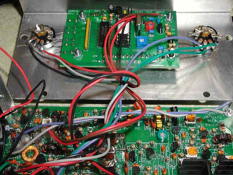
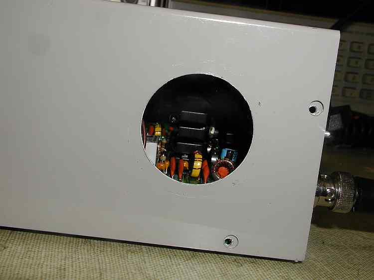
Here's the inside. The bitx board you recognize. On the front panel is the FCC-1 frequency display. Notice how close the bitx board is to the front. It's almost touching. Also notice where the FCC-1 ends up when the box is assembled. It will be almost intimately familiar with the bitx board. Also, check to see the circuitry on the bitx board that is close to the FCC-1. Oops! That's the receiver rf amp and band pass filter. That's the most sensitive part of the bitx board to interference and what do you think the FCC-1 board has on it? A micro controller and an oscillator!
Welcome to woodpecker and birdy city!
Now, the fix, hopefully. We'll move the board back in the box so some shielding can be placed over the FCC-1 board and also give us a little more distance from the aviary!
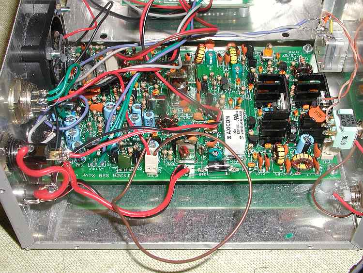
Looking at the rear of the box, there's plenty of room to move the board all the way to the rear and as far away from the digital display as possible. This thinking also applies to all of the other digital displays, not just the FCC-1
While we are here, the small fan seems like a great idea to keep the finals cool. You may need to select the fan carefully. This fan creates noise in the receiver. Try your fan out connected to the power source before drilling and punching holes. Be sure to wave the power wire for the fan all around the circuit board. Mine seems to be quieter in certain positions. This may make you believe that it's ok and when you finalize the placement permanently, the noise suddenly appears. That's what happened in mine. I didn't have any problem until I closed up the chassis.