Wide-Band Transformers In the Bitx
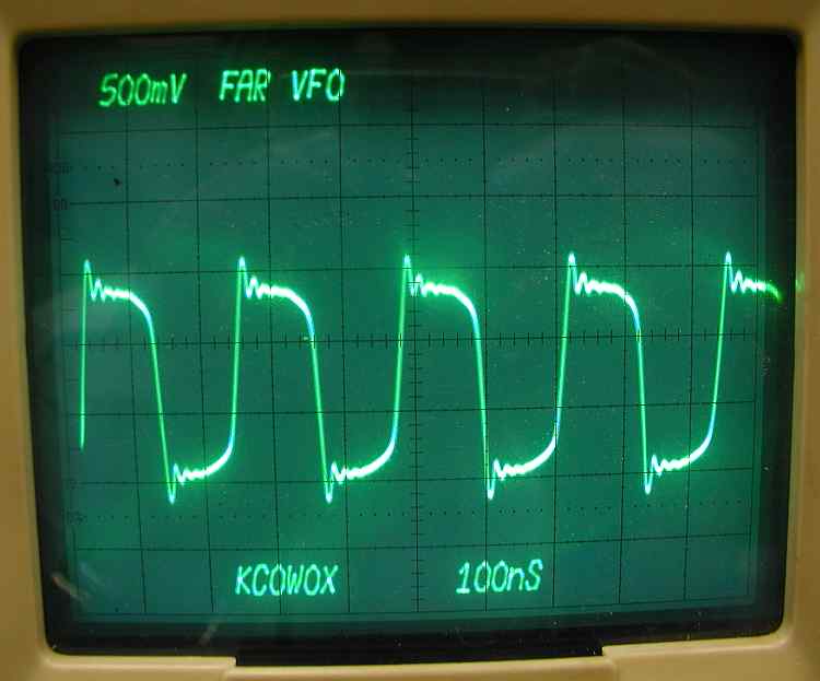
After building 3 different versions of the bitx and comparing the resulting waveforms throughout the transceiver, I have wondered why transformers were wound the way they were specified. In particular, the mixer-vfo transformer. I would have expected the vfo output to be a sine wave. At least that would keep the number of harmonics down. In fact, none of the waveforms looked that way. The original Farhan schematic only had 1 transformer feeding the mixer. The Far Circuits board followed that design and the vfo waveform fed to the transformer on the collector of Q7 looks like this.
Not much like a sine wave but not really horrible.
The version 3 board from Sunil came with some binocular cores. The specs said that T1 was 13 trifilar turns on a TV balun core. I took one of the smallest binocular cores and wound 13 turns on it. Not knowing what core material the supplied cores had, about all I could do was measure it. Measuring one of the resulting coils, I measured 69uH. Now Joe Carr in his RF Components and Circuits book, stated that the inductive reactance of the primary winding should be "at least 4 times" the impedance of the driving source. The measured 69uH of the primary winding would have 6.156k of inductive reactance. Checking at the collector of Q7, I found this.
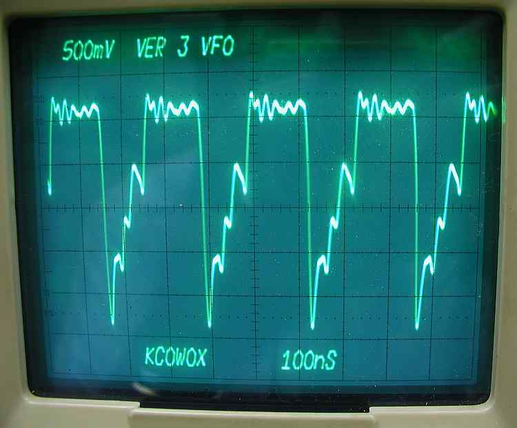
Now this waveform didn't impress me at all! It definitely wasn't what I expected. Trying to come up with an answer that seemed reasonable, I could think of none other than it might be an impedance match problem. Not knowing what the source impedance was feeding it, I decided that I would approach the problem scientifically. I'd just copy the transformer in another widely known bitx. The bitx20a kit.
The kit called for a FT37-43 core with 8 turns of trifilar winding. So I was back to the winding business and soon I had a brand new transformer in hand. Running the turns through the calculator at Kits and Parts web site I calculated 22.4uh. It measured 21uH. Usually the measured values are closer to the calculated than this was but this was good enough for a scientific test like I was setting up. Calculating the inductive reactance, it came to 1873 ohms. I installed installed the transformer on the board and fired up the power supply.
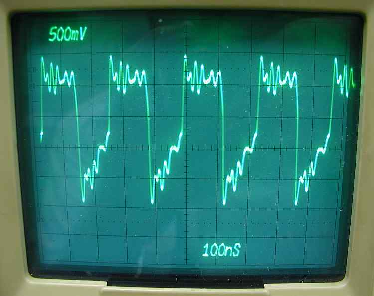
Now this looked a little better! Not a lot but at least it looked like I was going in the right direction. Taking turns off is a lot easier than adding them and I tend to believe in the old adage, "If a little is good, more will be better", so I un soldered it, took 4 more turns off now giving me a 4 turn transformer. After a trip back into the LC meter with a new measured value 5.25uH vs a calculated value of 5.6uH. This calculated out to 468 ohms of inductive reactance. I soon had it soldered back into the board and flipped the power back on.
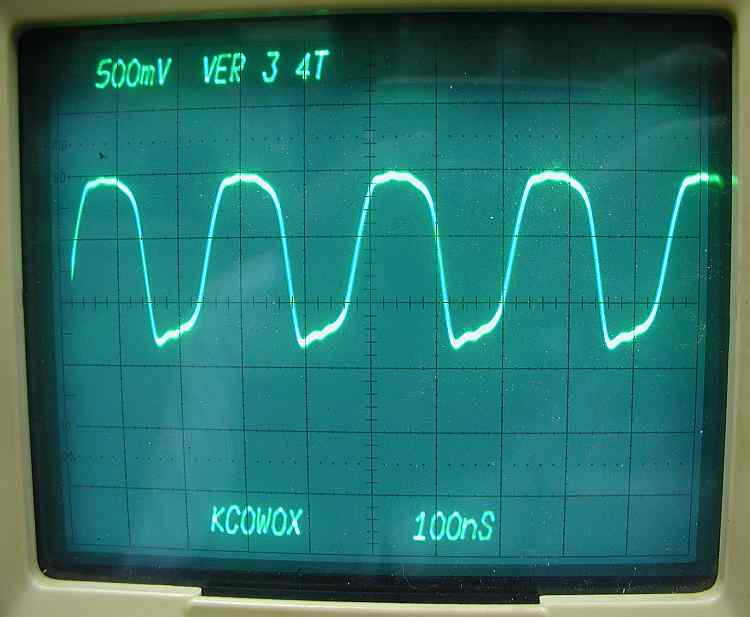
Now this looks a little more like what I expected right from the start.
What conclusion can we draw from all this experimentation? I believe that the difference between the Far Circuits waveform and the others may be due to only having 1 transformer in the mixer circuti. Beyond that, I have no opinnion. Maybe someone can give me a good explanation. If so, email me at Leonard and I'll be happy to add it to this page with credit given where due.